S12 - Megasquirting ~ empedocles99
2026-04-24 05:38:50Dunno if anyone cares, but I’m going to use this thread, over time, to detail my Megasquirt adventures in my mk1 1985 Notchback ca20e.
If you don’t know what it is, it’s an aftermarket fully tunable (and inexpensive) fuel and ignition controller. You can read up on it here: http://www.megasquirt.info/
I’m going to run megasquirt’n’spark on the megasquirt 1 v3.0 pcb, so I can control spark.
I bought my megasquirt hardware at: http://www.diyautotune.com
Hardware mods:
wiring harness plugs removed from spare ca20e ecu.
ka24e throttle body (on its way from ebay)
Spare ca20e distributor with rpm & throttle advance disabled (on its way, bought from COandCA)
Cold air intake build out of intercooler piping with vacuum lines added. Throttle body outside diameter is 2.5″, all my intake pipe is 2.5″, and the pipe will end in a k&n universal filter (RC-9420).
Electric fan out of a civic.
25W 5 Ohm dropping resistors 825F5R0 — OHMITE — Wirewound Resistor
ACDELCO 15292 Accessory Drive Belt 88934275 (to remove fan pulley, unconfirmed fit) (Is the fan pulley connected to the water pump? I never did this one)
I spent the weekend reviewing the megasquirt manuals, and FSM. I have most of the wiring down (subject to experimentation/verification, don’t blame me if you blow up your car, the ones marked with ? I am not completely sure of):
Stock CA20e pinout:
Looking at the back of the ECU where the harness plugs in, there are two plugs:
Left Plug:
115 114 —- 113 112
111 X X 108 107
106 X X 103 102 101
Right Plug:
10 9 8 7 6 5 4 3 2 1
20 19 18 17 16 15 14 13 12 11
Pin, Color, Description
1) (P) ??? Check Engine Light (Couldn’t determine exactly what this is for)
2) (W) Intake Air Temp
3) (Y/G) Coolant Temp
4) (B) O2 Sensor +
5) (B) O2 Sensor GND
6) (Y/L) ? Common wire for Intake Air Temp and MAF sensor (assumed to be +5V or +12V)
7) (LG/B) ? Provides signal/power to: Power Steering Oil Pressure Switch, Heater Fan, “Lightning Switch”. I am not sure if this needs to be connected or not.
8) (G/Y) Throttle Position Sensor switch: idle
9) (B/Y) Start signal in to ECU (+12V when START in ignition switch)
10) (L/W) Throttle Position Sensor swtich: full throttle
11) (G) MAF #1
12) (G/R) Throttle Position Sensor switch: Ecu output (assumed to be +5V or +12V)
13) (Y/R) A/T Unit (I assume this means Automatic Transmission)
14) (G/OR) Transmission Neutral Switch (GND when switch is on)
15) (L/Y) MAF #2
16) (Y/R) MAF #3
17) (G/R) Distributor output signal (controls the twin/single spark system, and also modifies timing in the Auto Trans model)
18) (BR) Check Connector (Not used)
19) (LG) Check Connector (Not used)
20) (L) Tachometer signal101) (W/L) Injector #4 GND/Signal
102) (B) Ground
103) (B) Ground
106) (B) Fuel Pump GND/Signal (Should be connected to a relay! Megasquirt can’t deal with the current on this wire)
107) (W/R) Injector #1 GND/Signal
108) (B/W) Injectors +
111) (Y/W) Idle Up (turns on under high electrical load to stabilize idle)
112) (W) Injector #2 GND/Signal
113) (Y) Injector #3 GND/Signal
114) (L/R) Air Regulator (Should be on when fuel pump is on, according to FSM)
115) (LG/B) EFI Relay switch signal
Megasquirt wiring:
Megasquirt is wired using a DB37 cable (a serial cable using up to 37 wires).
See here for reference: http://www.megamanual.com/ms2/V3assemble.htm
Here is how I plan to wire, notation is Megasquirt Pin -> ca20e wire harness pin:
MS ca20e
7, 8, 9, 17, 18, 19 -> Engine Block Ground
20 -> GM Air Temp Sensor in custom cold air intake
21 -> 3
22 -> ka24e TPS pigtail (variable resistor)
23 -> 4
24 -> 20
26 -> ka24e TPS pigtail (variable resistor)
28 -> 115 (main relay power)
30 -> 111
31 -> Coil #2 Negative Terminal (instead of distributor)
32 -> 101
33 -> 107
34 -> 112
35 -> 113
36 -> Coil #1 Negative Terminal (instead of distributor)
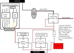
37 -> fuel pump relay: 114 (air regulator) + 106 (fuel pump) (I am going to wire in a relay in to the wiring harness to deal with these, since the OEM Ecu can handle more current from 114 and 106 than the megasquirt can for these pins… there is no fuel pump relay in the car, essentially, and megasquirt requires one).
Fuel Pump Relay:
One each of the switching wires connected to: (ca 115) Positive and (ms 37) Gnd/Neg
The ‘Switched On’ wire connected to: (ca 114 & ca 106) Positive
The ‘Common Switched’ wire connected to: (ca 102) Gnd/Neg

MegaSquirt assembly notes
Megasquirt 1 CPU on v3 pcb:
http://www.megamanual.com/ms2/V3assemble.htm
22) I did not install the IAC stepper control, since we have on/off idle air equipment on the ca20e.
50) It says you must choose between
1) Hall/Optical/etc. or
2) VR (Variable Reluctor)
We have a distributor/points system, so you should do 50a or 50b. 51 is optional in the case of ca20e (and won’t be of any benefit unless you swap to a different engine with VR)
You must then choose one of:
a) Hall/optical or points without a coil connection (ie.: Megasquirt drives the coil) or
b) coil negative terminal/points trigger
I chose (a) because I plan on using Megasquirt to trigger the coil, not the distributor. I am not completely sure on this, but because the mk1 distributor runs an IC to trigger the coils anyways, then you may be able to always just choose (a) even if you are not triggering the coils with Megasquirt.
50a) It says that most people don’t need D2, but it should be jumpered. I installed it, on accident. I will remove and jumper this location if there is a problem.
51) Did not install the Variable Reluctor circuit (even though it was recommended, it is optional if triggering off of distributor points)
52) Install the jumpers “For the Hall sensor, optical sensor, coil negative terminal or points”
54) This is needlessly confusing, just install the two resistors and go to the next step.
Use megatherm to program the air and coolant temperature sensors if you’re using the stock ones. From the 1985 FSM:
Air temp sensor resistance (kOhm) (ca20e only):
-10C -> 8.0-10.0
20C -> 2.3-2.7
50C -> 0.7-0.9
Coolant temp sensor (kOhm):
-10C -> 8.5-9.5
20C -> 2.3-2.7
50C -> 0.77-0.87
80C -> 0.30-0.33
65) Did not complete yet, but here is how I will do it:
Since the ca20e has two coils, we need to install a second coil driver. See: “Two Coils Direct Drive Output for a V3.0 PCB” on the Megasquirt ‘n’ Spark Extra Manual. The only difference is that I wired the coil output to pin 31 (instead of pin 6 as in the manual) because my wiring harness already had an unused wire on pin 31 that I could use.
Reference notes:
Megasquirt Manual v3.0 pcb
Megasquirt ‘n’ Spark Extra Manual
240sx Distributor Wiring
69) I screwed this part up a little… the mica insulators are in a bag with a screw, lock washer and plastic washer. The mica insulator are clear rectangles with a hole cut in them.
69,70) Install both (in case of injector upgrades later, and I don’t know if we have low or high impedance injectors anyways)
71) Do not install these. Even though it’d be nice to have the current protection, we need the heat sink space for a second coil driver.
Useful Specifications
Fuel Pressure Regulator: 30 psi at idle, 37 psi at full throttle
Fuel Pump: 43-64 psi, 95 liters/hour or 25.125 gallon/hour (good to at least 150hp or so)
Fuel injector impudence: 2-3 Ohm (low impedance)
Updates
May 24, 2007
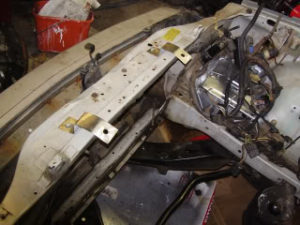
I got the parts for the cold air intake (universal intercooler piping kit for my eventual ca18det). I ripped out the maf, the stock intake pipes, the stock fan and fan clutch.
I mocked up the cold air piping and marked where to attach vacuum lines.
I got this rad set of vacuum line taps: “Spectre 8711 Optional Air Intake Installation Hardware Kit” off of (Amazon).
It’s a set of grommets and vacuum fittings to connect vacuum lines to intake pipes, you just drill a hole and pop a grommet in.
Oct 25, 2007
Here’s a link to a baseline tune that should get the car started. It’s tuned for 12.5:1 AFR at 3000 rpms, and 12.0:1 above that.
http://www.indolence.net/s12/resources/meg…_2007_07_14.msq
I’ve decided to take it to the next step and drop a t2 turbo on this bad boy, I’ll make a writeup in another thread.
VG30 Carb Swap Guide
2017-01-06 04:22:47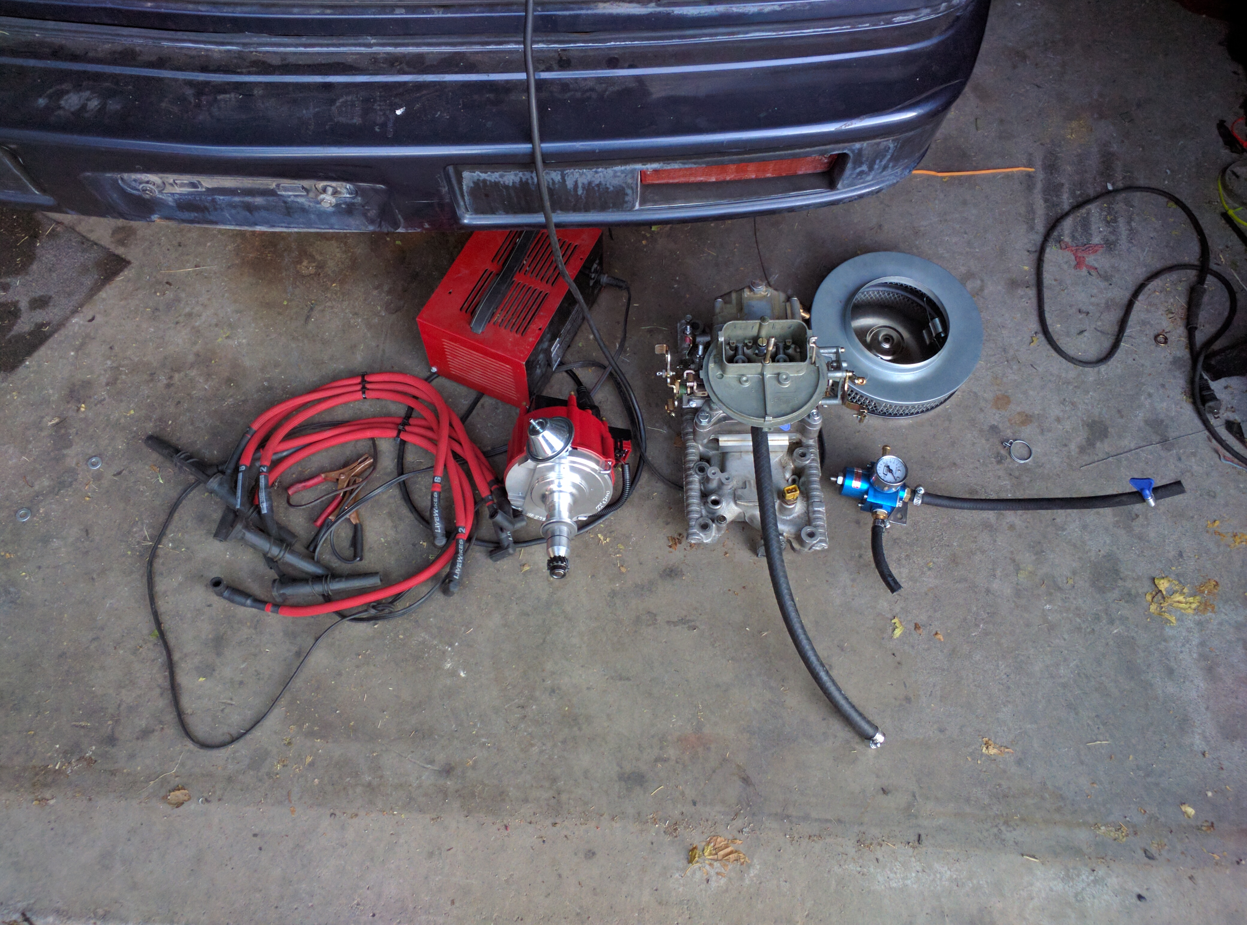
Carb’ing the VG30e is simple, it sounds trivial but it really isn’t. Now why the question is why? Well for one Datsun 510 Owner’s do this often already and this question has been asked on the cs12 forums a few times. Granted you will not get much of a different performance gain, just the satisfaction of doing something off the wall weird and different. It can be a performance changer if you need a full over haul of the EFI harness as it might also improve the old failing electronics.
I don’t intend to boost the vg30 s12 at all. If at most I might add some NOS down the line but there isn’t much I wanted to do from there. Going Carb, is just a different Fuel Delivery system that works.
I am trying to work together a small break apart the efi and install of the carb when I get my tripod in for the GoPro before I proceed with a live video on my process.
Parts:
- Distributor – best solution DUI Performance Distributors, secondary “Rare” Saudi Nissan vg30 distributor.. There is most likely another way but this is simple one.
- Fuel Pressure Regulator, you need a 3 way that supports 5psi or lower. I Used the Professional Products 10652 Blue 3-Port Carburetor Fuel Regulator with Return Line
- Fuel Pump Re-wire Coming from efi you will also need to rewire the fuel pump to key on power and not ECU. I used the cs12 guide for KA24de swap.
- lower intake manifold from an mid 80’s Pathfinder, modified easy with this I sent it over to David Carroll with EE to modify it with adapting a Holley Carb
- Spacer 1 inch at least to rise the Carb high enough above the valve covers
- 350 CFM holley carb 2BBL (vg30 is an 181ci motor, a 350 is more than enough to cover)
- Hood Risers is needed to clear both the carb and the distributor.
- Extra 10FT of 14 – 16 gauge wires,
- Distributor hold down clamp to keep the distributor in place.
- Custom throttle cable setup; I was able to modify the universal one and used the bicycle cable as it fits much better and less snag in between.
Now for the only thing is needed at this point is knowing what wire does what, if you have done the PRW-2 Mod, you want to get the battery and the tach connection down you will be deleting all EFI related. If you want with the DUI Dizzy, the coil is a coil pack located on the top of the dizzy and only need 2 wires, 1 for the battery signal and 1 for the tach signal. 3rd wire you will need to find out the coolant temperature gauge. Using a continuity tester you can locate the wire easily to the body harness in you might need to get under the dash to 2 plugs and find the one that the engine harness connects to. You will delete the ecu and wiring harness completely from the car as it will not be needed, or if you are lazy wrap it in a pile and tuck it away but advised to remove the whole wiring harness.
Key note #1: when you collect the pathfinder intake manifold be sure to grab the mounting nuts and bolts and don’t reuse the SEv6 as they are different in length. I made this mistake that had me go back to pick a part to acquire the right bolts. the studs are recommended to change them out as well as they are a different size on the pathfinder but you can get away with it as you don’t need to massively torque down the intake just follow the FSM procedure for the pathfinder.
Key note #2: When ordering the Dizzy, be sure to have them verify that the vacuum advanced is setup with the correct rotation as I had to send mine back because of the vacuum advanced was setup wrong. These distributors are a clone to the MSD Street Fire Dizzy setup, the coil pack, the module, cap and rotor are replaceable with the MSD replacements they recommend to order theirs. When you also order the dizzy get the live wires. and have them trim about 2 inchs off of the 5 and 6 cyl and 1 inch of the 3 and 4 cyl.
Key note #3: Jetting, if you are unsure what jets to help tune your setup, you can purchase the Percy Adjust – a – jet adapter it will help you narrow down your jet sizing.
Key note #4: EGR, anything that was utilize for the EFI will be deleted, you will need to plug up the various holes including the EGR tube on the passenger side, the narrowband O2 sensor, in it’s place I recommend installing an AEM Wideband for much easier adjustments to the fuel delivery. There will be other weird and strange EFI devices located all around the engine bay that you will also be deleting. The oil breathers you will be deleting and adding filters in its place on the valve covers.
I will update this Howto as I progress and upload the videos as I proceed to go from EFI to carb again for the 3rd time. And if there is anything I am forgetting in this, i will proceed to update the original post.
KA24E and KA24DE Swap for the S12
2017-01-05 20:56:32KA24e/de are nearly the same for the swap only real difference is the wiring.
One side note: This swap can come off as confusing and hard to understand.
One keynote I found was a video, this video helps with the wiring issues.
https://youtu.be/7DEQZRBq-Fc
FSM recommended to locate the one for the ka swap pulled (240sx s13 – s14)
NicoClub.com/fsm
A few guides in this will be the following, CS12 provided the most information for this topic but even that is a bit unclear to some.
KA Swap Guide:
http://club-s12.org/retro4/index.php?topic=29782.0
KA DOHC Swap guide:
http://club-s12.org/retro4/index.php?topic=21003.0
KA SOHC Swap guide:
http://club-s12.org/retro4/index.php?topic=25320.0
S12 to S13/S14 W71c transmission guide
note: mk2 models just need the transmission and the front half of the drive shaft and it will bolt up.
http://club-s12.org/retro4/index.php?topic=29974.0
some other key notes provided by NicoClub that can be helpful is the s13 SOHC to DOHC swap. Only the helpful part is the wiring.
http://www.nicoclub.com/archives/ka24e-to-ka24de-swap-step-by-step.html
//Printable pdf coming soon.
CA18DET Swap.
2017-01-05 20:34:51//details how to swap in an CA18det
There is a few guides out there how to swap in the Motor set.
Sam’s post from 2006 – Download PDF – Club-S12 – 18det S12 Swap Guide
Link to the guide is here: http://club-s12.org/retro4/index.php?topic=14859.0
Some key notes this guide pretty much tells you that with the motor mounts from your previous motor IE: Ca20e or CA18et will bolt up, motor will align just fine.
To add in any CA 20/18 c trans will bolt up as the bolts match the engine. Main confusing part is the wiring.
Keynote to add: Alot of the wiring guide can be bypassed with this harness by Wiring Specialties
This is far the easiest motor swap I have seen and researched.
Important notes about this thread:
1. The information in this thread may not apply to your year/engine S12. As such, it is recommended you use the information in this thread in conjunction with information provided in an S12 FSM/180SX FSM
2. This thread will be edited and updated from time to time with information regarding the wiring/components for different years/engine configs of S12s as they can be different. If you find something different in your swap from the information provided in this guide, please pm me, an mod, or chat me up on msn messenger, email addy is theultimateinsanemonkeyisinyourhouse@hotmail.com
3. As always, the writer of this guide, and the club that is hosting it on the forum are not responsible for any loss of money, time, loved ones, or valuable limbs that may arise during the long arguious (sp?) battle that is the CA18DET/S12 Swap.
Table of Contents
Section 1: Tools recomended/needed for swap
Section 2: Removing your engines
Section 3: What to do once your engine is removed
Section 4: Wiring
Section 5: Install
Section 6: Misc. recommended components
Section 7: Helpful links with more information
Section 8: Current CA18DET facts and mythsSection 1 Recommended tools for swap
Welcome to the exciting world of the 18det/s12 swap. With you just starting out here is an brief list of tools/literature you will need to get going on your swap.
1. An socket set of some kind, doesnt matter which kind as long as its got like 10 mm all the way up to 22mm 23mm or so.
2. An set of open end wrenches, ranging in size as same as the sockets.
3. An set of ratcheting wrenches is recommended, but many times you can get away without.
4. An pipe that will fit over your ratchet handle that you can use as leverage for those more reluctant bolts.
5. Screw driver set with many different sets of bits.
6. Engine hoist, engine stand, jack, and jack stand.
7. S12 fsm for your appropriate year car, and 180SX fsm
8. An digital camera is nice if you run into any problems, or find out something that was originally said on the forum couldnt be done, to prove us wrong.
9. Torque Wrench.Section 2: Engine Removal
1. Jack up car, drain rad fluid, oil, and transmission fluid.
2. Disconnect rad hoses, unbolt mount holding up driveline before transmission.
3. Set jack under tranny, raise tranny up an bit, then undo transmission mount bolts, slowly let transmission down.
4. lower car, disconnect engine harness, disconnect clutch slave, remove rad.
5. Find an place to hook engine hoist to engine, jack engine up slightly, unbolt engine mounts.
6. Meanuvre engine/transmission out of car and set in corner of shop.Repeat process for front clip if you purchased front clip, if you have an motorset then dont worry about it.
Section 3: What to do once your engine is removed
You now have your stock engine/trans sitting in the corner of your shop and your ca18det sitting somewhere else in your shop…whats the next step? It depends on your scenario.Scenario 1, You purchased an front clip, your CA18DET with C transmission are sitting on your shop floor.
First step, remove your 18det from its C transmission, and put your 18det on an engine stand. Next you need to replace the following, timing belt, head gasket, and water pump. Once that is done you need to take your engine off the engine stand, replace the clutch, then bolt it back up to your transmission. If you have some extra money, it is also recommended to replace the exhaust dumpipe at this time to as once the engine is in there is no real room to remove it and replace it…also you can get an larger one then stock.Scenario 2, You purchased an motor set. First thing you need to do is put your 18det on an engine stand and replace everything that you would in scenario1. Normally with an engine set, they sell you the C transmission that came on the engine. If for some reason your engine is without the transmission just remove your stock transmission and mount it to your CA18DET.
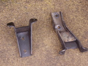
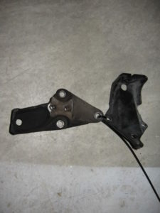
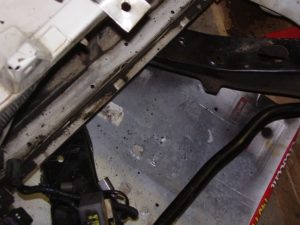
Another thing to note is that on my engine my brackets where the same on my 18det as the ones on my 20e, which looked like this
Your brackets however may look like this, if they do, your stock ca brackets will mount to the block.
Also if you swap an S13 trans into an S12 MkII, it will bolt up to the S12’s trans mount, but you will need the front half of an S13 drive shaft and bolt that up to the back half of the S12’s. If you swap an S13 trans into an S12 MkI, you will need a custom trans mount. As for the driveshaft, I don’t know, but the technique for the MkIIs might work. Or a custom 1 or 2 piece drive shaft may have to be purchased. (thanks to nemesis for mentioning this and needcafors13 for discovering this on his S12/KA drift car.)
Section 4: Wiring
Before I go head on into wiring, I think its important to point out the things needed to make everything work. These are things you should look for if you are buying an engine set, or front clip. If you end up having to buy an used harness because you couldnt get one with your engine you will want to ask about these also.
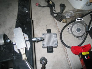
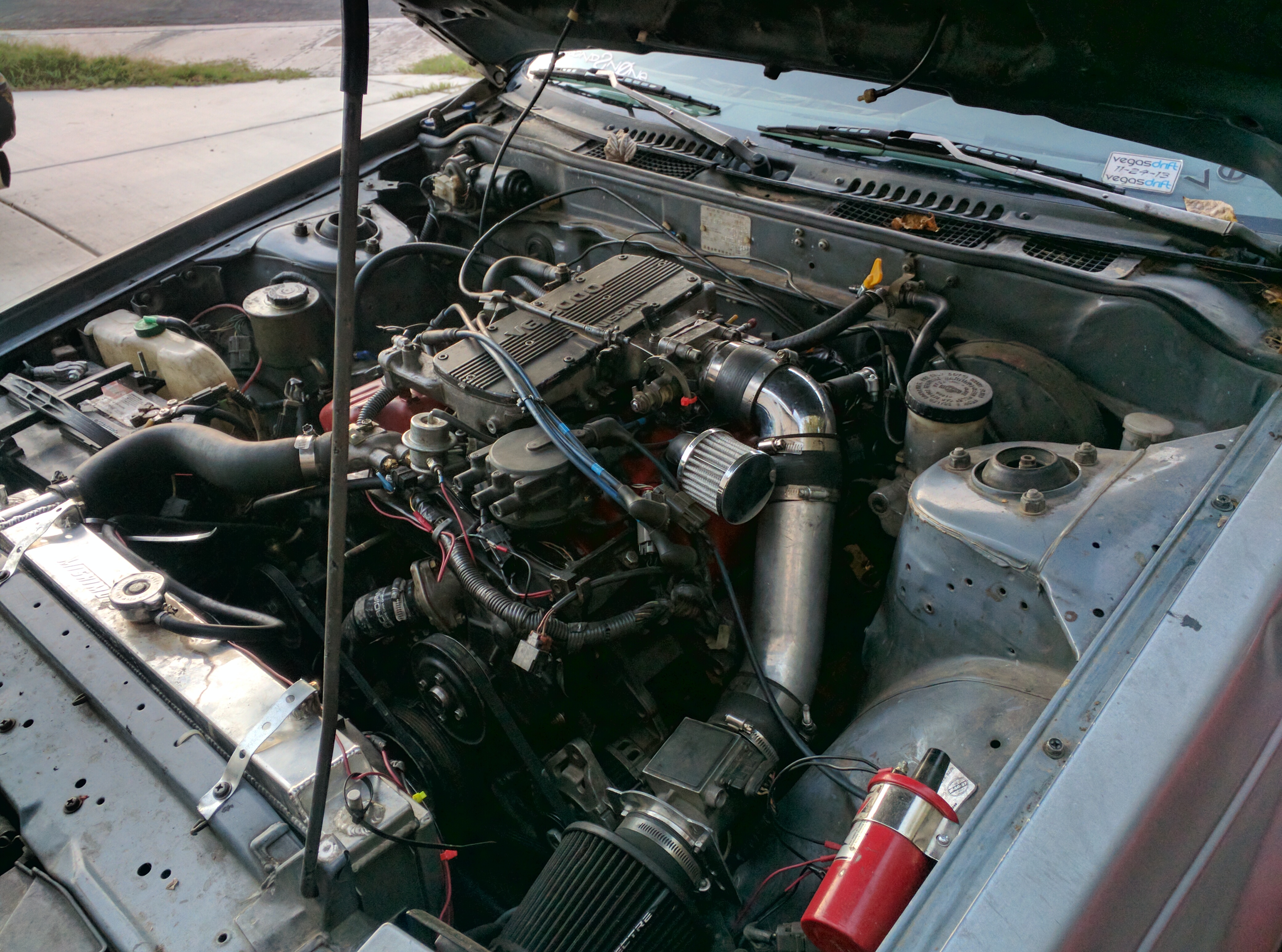
Now naturally the system isnt to much different from the stock system…you have the engine harness, the maf, and the ecu. But you also have an ignitor and an dropping resistor. The dropping resistor looks like this
It is the silver rectangle box on the left. (note, if your harness did not come with an dropping resistor you can use an dsm dropping resistor(1st gen dsm…IE 90 Eagle talon or eclipse), the write up for that is in the myth section.) And here is an pic of an ignitor, it is the silver box with ribbed protrusions on the outside of it above the engine mount
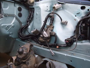
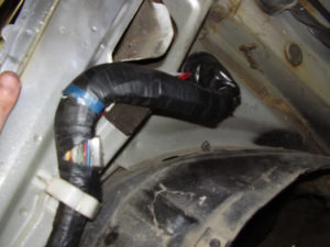
As for harness routing, this is how I have done it on my 85 lhd usdm s12
I pretty much routed it thru the same way the 20e harness runs. There is an plastic elbow piece inside the 18det harness tho that I removed by untaping the harness, removing it, then retaping the harness. This allowed me to gain an couple of inches on my harness. Now for the fun part…the wiring.
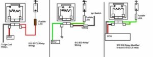
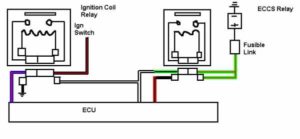
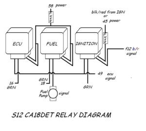
Here are some relays wiring diagrams, The KA/s12 wiring schematic and SR/S13 wiring schematic are less important, but are a good reference, and also are nice to have if you have a friend who might want you to help them with a swap.
Another important thing to remember, that isnt always shown in the wiring diagrams is that you should have a fuse and a fusible link inbettween each relay and its power source. A lot of people right now are just using fuses, and no fusible links and are getting away ok with it, however the fusible link is a good safety precaution to keep your ecu from getting fried.
The below is previous wiring info, and should only be used in comparison with the relay diagrams, follow the diagrams tho, if the below doesnt match them, follow the diagrams instead.
Yellow/red wire on the s12 harness goes to the black and red wire on the 18det harness, this is for the fuel pump relay
blue/red wire on the s12 harness goes to the reb and black wire on the 18det harness, this is ecu relay
black/red wire on the s12 harness goes to the red wire on the 18det harness, this is ecu back up power
blue wire on the s12 harness goes to the black/blue/red wire on the 18det harness, this is the main ignition power
green/black wire on the s12 harness goes to the black white wire on the 18det harness, this the ecu power
black/yellow wire on the CA18det harness, which is the idle air valve power, along with the o2 sensor which is the brown wire, both go to any 12 volt switched source.
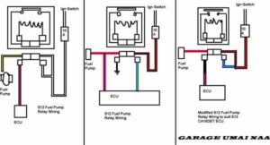
The neutral switch on the CA which is green/orange goes to the neutral switch on the s12 harness which is also green/orangeFor more clarification on the wiring, you should look at the ka/s12 swap and the s13/sr swap. The KA/S12 swap looks like this:
and the s13/sr swap looks like this:
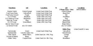
ECU & Dash wiringThe colors on the wires that run from the ECU up into the dash matched up perfectly on both the SR ECU harness and the KA dash harness:
Wire Color
Use
Yellow / Red stripe
Tachometer signal
Yellow / Green stripe
Speedometer signal
Orange
Ignition start
Black (may be more than one ground)
Ground
Blue / Green stripe
AC signal
Blue / Black stripe
Water temp signal
On the mk2 s12 there is i believe 2 or 3 white plugs underneath the dash that you need to splice into certain wires into the ecu, but those wires are previously mentioned in the write up. In the mk1 there is one or 2 plugs that you need to splice wires off of. As of right now I am a little unsure on both mk1 and mk2 plug counts. I havent started on my wiring yet, but as you can see I have almost all of the info. If you have done either swaps, please post up pics and or info for your model/year/engine of s12.
If your car started with an mechanical speedometer, your speedo cable will connect right up to the 180sx C transmission, I belive that if you have an digital dash, it doesnt use an mechanical speed sending unit in the transmission so you will need to try to come up with an solution to that. Your stock tachometer tho will not work with the 18det as it sends the signal back off the coilpack differently then the 20e or 18et does from its normal coil. An solution for this is to use 4 IN4004 diodes connected to the coil side of the ignitor, then join them together to the 4 on the tacho side, and join the wire going to the tacho making sure the arrows on the diodes are pointing towards the tachometer and away from the coil.
Section 5: Install
The installation of the engine should be pretty straight forward from here. Put the engine/trans back into the bay and install everything back up in the reverse order from how you removed it. There are some components that you will need, and some that are recommended which I will cover in the next section. It is recommended to install your engine, then do the wiring first tho so you dont end up taking to much distance out of the 18det harness. But once the engine is installed and the wiring is done, only thing left to do is have the exhaust made up by an local shop, and pick up a couple components to make the car run a bit better.
Section 6: Recommended Components
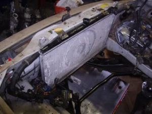
Stock the 180SX came with an smic (side mount intercooler), now this is better then having no intercooler, but it is an good idea to upgrade to an fmic, especially if you install an boost controller and start running higher boost then stock. And if you only bought an motorset…you will prolly not even have the smic. An BOV (blow off valve) is also an good thing to have. Along with an oil cooler, and an oil catch can. It is possible to also use either the 180sx rad, or the 20e rad, here are some pics of my 180sx rad install:
It is also recommended to pick up an aftermarket oil temp gauge, and boost gauge.
Section 7: Helpful links with more information
These are all on www.nicoclub.com in the CA section stickied by one of our own club s12 members who happens to be an moderator on nicoclub.com, needcafors13
CA18DET Engine Facts
http://forums.nicoclub.com/zerothread?id=114950FAQ’s, Common upgrades, D.I.Y. upgrades, no-no’s, etc…
http://forums.nicoclub.com/zerothread?id=114953Part Numbers / Crossover Parts between USDM and JDM CA18’s
http://forums.nicoclub.com/zerothread?id=114952CA18DET Wiring Information and FSM
http://forums.nicoclub.com/zerothread?id=114956Catch Can Installation Info:
http://forums.nicoclub.com/zerothread?id=13750Other links tho to look at for more information regarding variations in european and australian engines would be http://www.sxoc.com and the australian s12 site.
Section 8: Current CA18DET Myths:
There are a couple of myths floating around this forum and others about certain things regarding the 18det.
One of them is that an dropping resistor from an 1st generation dsm (IE eagle talon, or eclipse, awd turbo.) will work with the 18det harness. As of yet, no one has given me anymore solid info…IE the part number for an dsm dropping resistor, and wether or not it has to be wired up any differently, or if it will plug right into the harness.
[Edit] This myth has been resolved, an big thanks goes out to MasterZenki off of nico for doing an quick write up on how to make the dsm dropping resistor work with the ca18det harness…and here it is.So if for some reason your harness didnt come without an dropping resistor this will work for you.
Another myth, that was floating around, but has been proved wrong is that the mk2 rsx in japan didnt come with an CA18DET. However, it did come with an 18det, and also the s12 in japan was built into the early 90s. The s12 18det differs from the 180sx 18det in that its throttle body goes over the valve cover like the 18et. The engine also has 8 intake runners and came non intercooled. The engine used one coil pack to power all 4 plugs instead of individual coil packs.
Another myth that was going around on this forum was that the 18det wouldnt bolt up to the B transmission. Despite many australian members claiming that it bolted up fine. I myself didnt know for sure…and knowing what I know about the car I thought it possible that the B tranny in australia might of been different then the usdm or canadian, but my b tranny bolted up to my block without issue.